
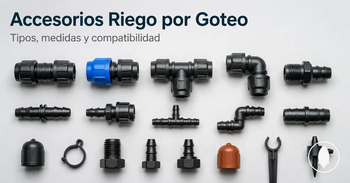
Drip irrigation fitting parts, names, and connection roles
Drip irrigation fittings are connector components that join, branch, turn, adapt, reduce, or close sections of a tubing line. Fitting names become clearer when each part is understood through its connection role rather than only its shape. This role-based view explains how fitting parts relate to the flow path within a drip irrigation system.
A tubing line can include different connection points where a fitting changes the path, creates a branch, connects different formats, or closes an open end. Common role families include couplers for joining tubing sections, tees for branch connections, elbows for direction changes, adapters for transitions, and end caps for closure.
Fitting names matter because they describe the function a part performs at a connection point. Size, installation, and layout are related checks, but they are separate from identifying the role of each fitting part.
Fitting parts are connector components within a drip irrigation system, not every system component. Tubing, emitters, valves, and other parts may connect with fittings, while the fitting itself describes the connection role it performs.
What drip irrigation fitting parts do in a tubing line
Drip irrigation fitting parts are connector components that join, branch, turn, adapt, reduce, or close tubing paths. Each fitting part has a connection function that affects how a tubing line is arranged and how the flow path is directed through connected sections.
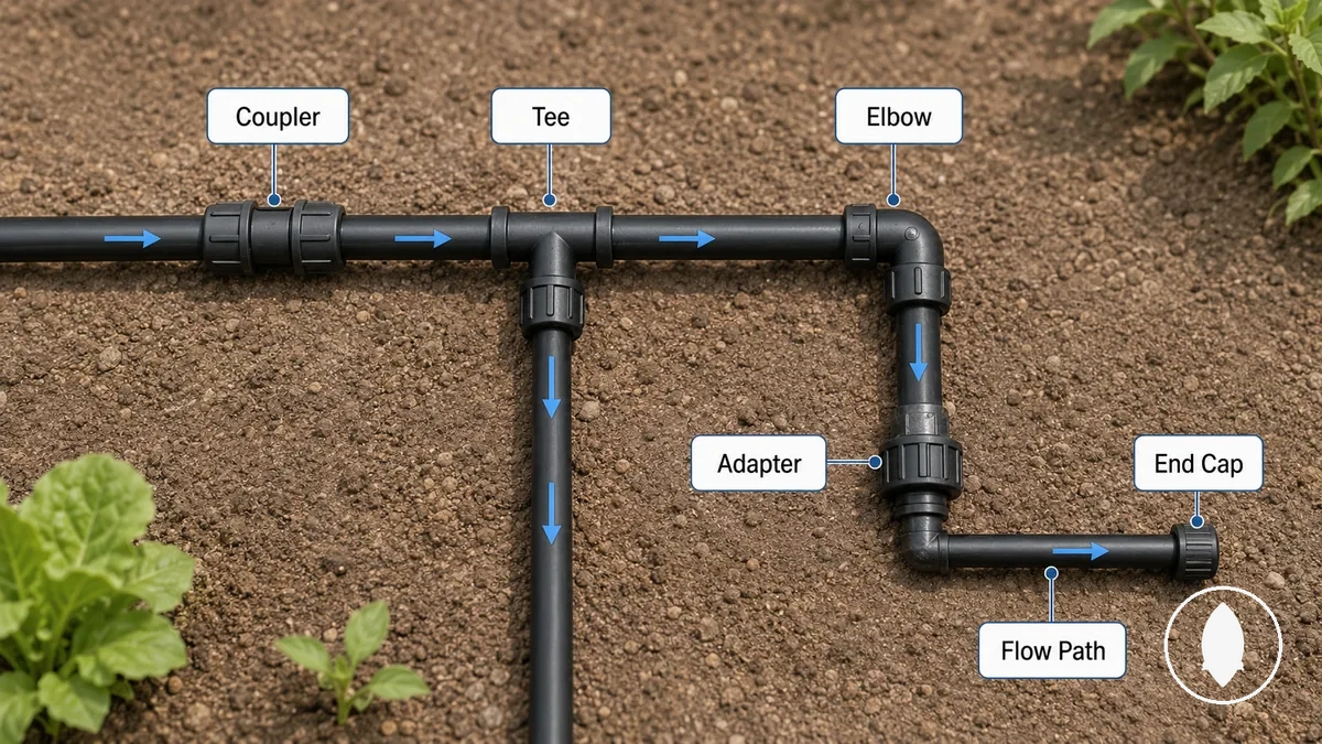
Drip irrigation fitting parts control connection points within a tubing line by changing how sections connect with each other. For example, what fittings do in a drip system depends on whether a part is used to join tubing sections, create a branch, change direction, make a transition, or close an open end. Couplers support joining, tees support branch control, elbows support turns, adapters support transitions, and end caps support line closure.
Fitting parts are connector components, not the same as every drip irrigation system part. Tubing, emitters, filters, pressure regulators, and valves may work alongside fittings, while each component has a separate role within the system. The exact connection result can depend on the fitting style and tubing condition.
Fitting parts versus other drip irrigation system parts
Fitting parts are connector components, not every drip irrigation system part. They define how sections connect at a connection point, while other system components perform different functions within the tubing line and flow path. This boundary separates connector roles from surrounding irrigation parts.
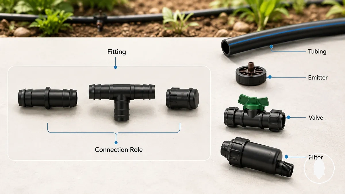
A user may identify multiple parts when looking at a drip irrigation line, but each part has a different role. Fitting parts focus on joining, branching, turning, adapting, reducing, or closing connections. Tubing carries the line path, while emitters, valves, filters, pressure regulators, and timers support other system functions.
| Item | Primary role | Is it a fitting part? | Boundary note |
|---|---|---|---|
| Fittings | Connect tubing sections or change connection paths | Yes | Defines the connector role at a connection point |
| Tubing | Carries the flow path between connection points | No | Provides the line section that fittings connect |
| Emitter | Releases water from the irrigation line | No | Performs a different function from connector parts |
| Valve | Controls water flow in the system | No | Controls flow rather than joining tubing sections |
| Filter | Supports water quality management in the system | No | Supports system operation rather than acting as a fitting part |
| Pressure regulator | Helps manage pressure conditions | No | Has a different role from connection parts |
| Timer | Controls watering schedules | No | Relates to operation rather than connector function |
The main distinction is that fitting parts describe connector roles, while other drip irrigation system parts support different functions around the line. Some components may combine functions depending on their design, so the role should be identified from the connection point and component purpose.
Main connection roles by fitting shape
Fitting shape is a clue to the connection role a drip irrigation fitting performs in a tubing line. The shape helps identify whether a part is used for a straight join, branch connection, direction change, transition, or line closure. These connection roles explain how different fitting forms relate to their purpose.
When selecting a role at a tubing point, the fitting shape can help identify how a connection changes the line condition. The table below maps common fitting shapes to their connection roles, typical line positions, and practical outcomes.
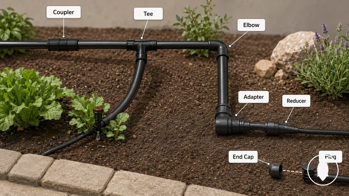
The relationship between fitting shape and function helps separate shape roles from broader fitting categories. See fitting types explained for how fitting groups are organised beyond individual shape roles.
| Fitting shape | Connection role | Typical line condition | Practical outcome |
|---|---|---|---|
| Coupler | Straight join | Two tubing sections need a direct connection | Joins sections along the same tubing path |
| Repair coupling | Straight join at a repair point | A tubing section needs a connection change | Creates a connection between tubing sections |
| Tee fitting | Branch connection | A line needs an additional branch path | Creates a branch from the tubing direction |
| Elbow fitting | Direction change | Tubing needs to turn at a connection point | Changes the direction of the tubing path |
| Adapter | Transition connection | Different connection formats need to connect | Creates a transition between connection types |
| Reducer | Size transition | A connection requires a size change | Links sections with different size conditions |
| End cap | Line closure | An open tubing end needs to be closed | Closes the end of a tubing line |
| Plug | Opening closure | A specific opening needs to be closed | Stops flow through the selected opening |
| Goof plug | Hole closure | An unwanted opening needs to be closed | Creates a closure point for the opening |
Couplers and repair couplings for straight tubing joins
Couplers and repair couplings are straight-line join parts that connect tubing sections along the same path. A coupler provides a straight tubing join, while a repair coupling is used when a cut tubing section or repair point needs a new connection.
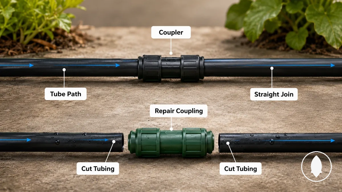
A cut tubing section or tubing extension can require a straight tubing join to maintain line continuity. A coupler focuses on joining same-line tubing sections, while a repair coupling focuses on connecting at a repair point. The connection outcome can depend on tubing size, fitting design, and tubing condition.
Tee fittings for branch connections
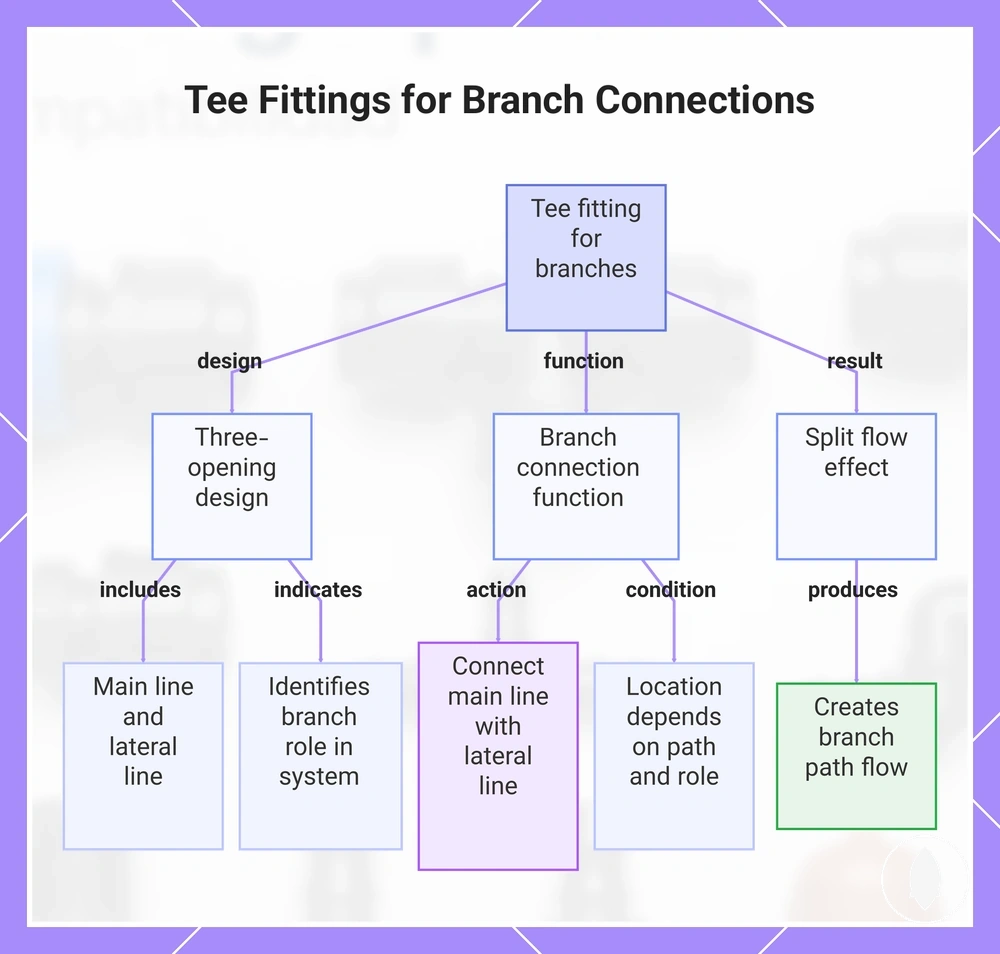
Tee fittings are parts that create a branch connection from one tubing line into another path. A tee fitting has three openings that allow a main line connection and a separate tubing branch. The three-opening shape identifies its branch role within the tubing system.
A tee fitting can connect a main line with a lateral line where a branch connection is needed. The connection point creates split flow through the branch path. The exact branch location depends on the tubing path and the intended connection role.
This chart explains the design, function, and flow of a tee fitting used to create a branch connection in a tubing system.
Elbow fittings for direction changes
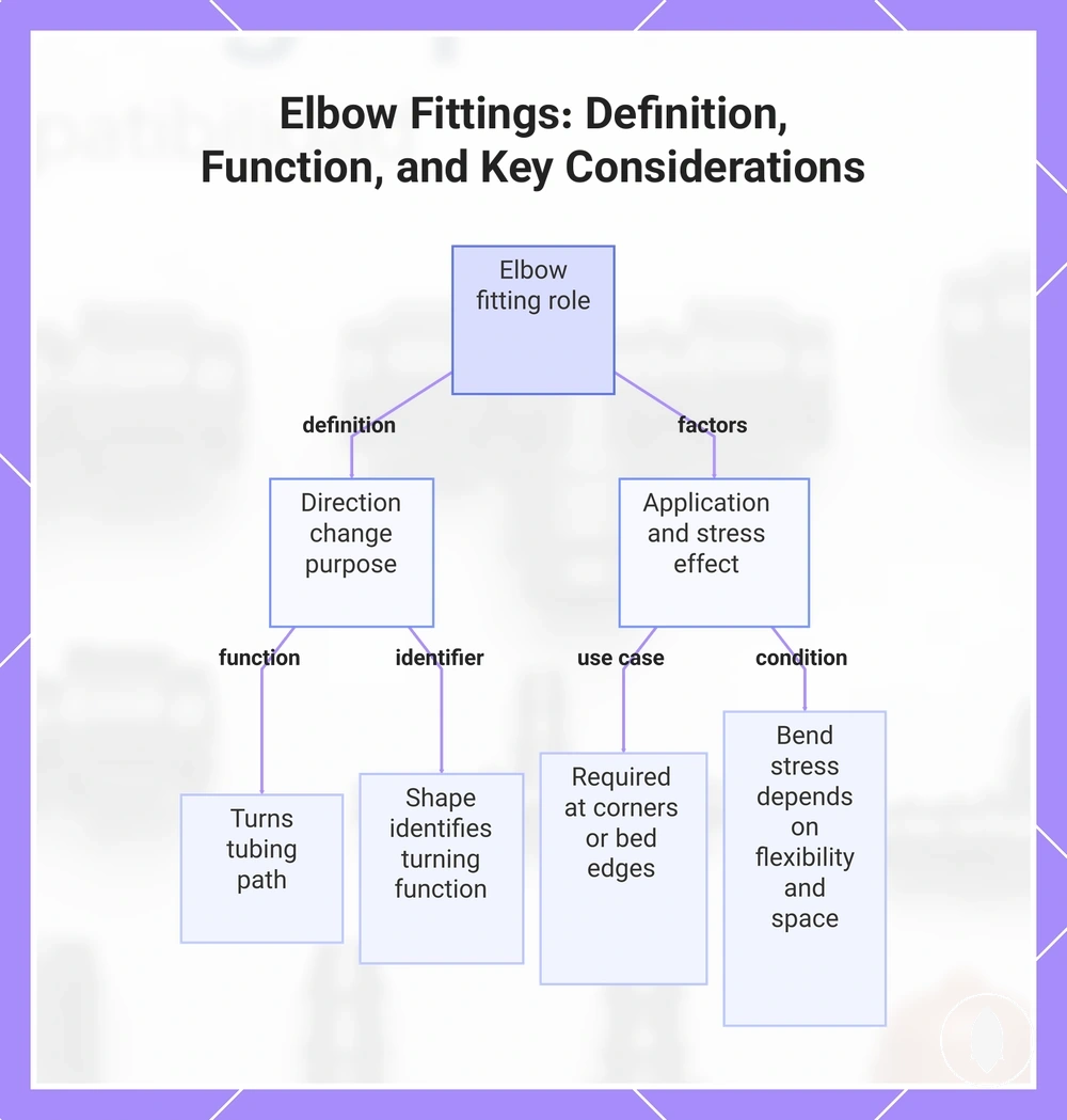
Elbow fittings are parts used to create a direction change in a tubing path. The angled shape of an elbow fitting allows a connection point to turn the tubing path while keeping the focus on its connection role. The shape identifies the fitting's turning function.
A corner or bed edge may require an elbow fitting when a tubing path needs to change direction. The angled shape can help create a cleaner path, while the effect on bend stress depends on tubing flexibility, available space, and the specific connection condition.
This chart defines elbow fittings, explains their role as direction change connectors, and highlights practical factors for their use.
Adapters and reducers for format or size transitions
Adapters and reducers are transition parts used when a direct connection does not match. An adapter handles a format transition, while a reducer handles a size transition. The difference depends on whether the connection needs a change in connection style or a change in size relationship.
A threaded connection joining to a tubing connection is a local example where an adapter may provide a format transition. A larger-to-smaller tubing connection is a local example where a reducer may provide a size transition. The connection outcome can depend on fitting style, tubing standard, and size tolerance.
| Part name | Transition handled | Common condition | Check before use |
|---|---|---|---|
| Adapter | Format transition | Different connection formats need to connect | Check the connection style and compatibility conditions |
| Reducer | Size transition | Different tubing sizes need to connect | Check the size relationship and fitting requirements |
End caps, end plugs, and goof plugs for stopping flow
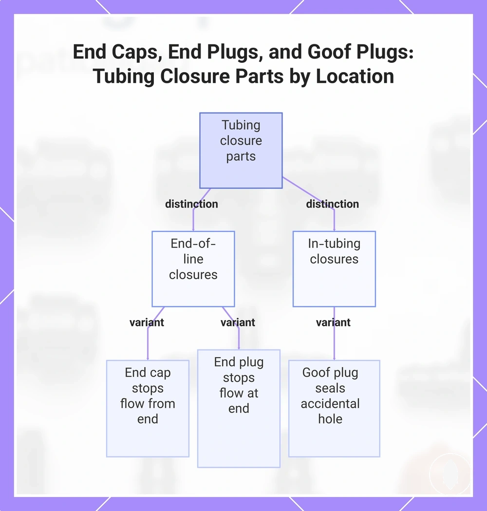
End caps, end plugs, and goof plugs are closure parts used for stopping flow in different tubing conditions. An end cap or end plug closes an open line end, while a goof plug closes an unwanted hole in the tubing. The main distinction is whether the closure point is at the end of a line or within the tubing.
A lateral line end may use an end cap or end plug when the open line end needs closure, while an accidental hole may require a goof plug to seal the opening. The sealing result can depend on tubing condition, hole size, and part fit.
- End cap: Used for an open line end and provides a closure point that stops flow from the tubing end.
- End plug: Used at a tubing end where stopping flow is required through an end closure.
- Goof plug: Used for an unwanted hole where a tubing opening needs a sealing point.
This chart shows the two main types of tubing closure parts based on where they are used: at the end of a line or within the tubing to seal an accidental hole.
Attachment ends that determine how fittings connect
Attachment ends are the physical interfaces that determine how a fitting connects to tubing or another source part. They define whether a fitting grips, threads, locks, or seals against a matching surface. The attachment end connects the fitting design with its grip method or thread mechanism.
Matching a fitting end to a tubing or source surface requires understanding the connection interface. The table below organizes attachment ends by grip method, matching surface, and fit caution.
| Attachment end | Grip or connection method | Matching surface | Fit caution |
|---|---|---|---|
| Barbed | Grip method using the fitting end and tubing connection | Tubing designed to accept the barbed end | Fit can depend on tubing size, wall thickness, and material behavior |
| Compression | Compression grip method around the connection area | Tubing or fitting surfaces designed for compression connection | Connection results can vary by fitting standard and tubing condition |
| Lock | Locking mechanism that holds the connection interface | Matching locking surfaces | Fit can depend on the specific components being connected |
| Push-fit | Push connection that engages the fitting interface | Tubing or connector surfaces designed for push-fit connection | Fit can vary with tubing condition and fitting requirements |
| Threaded | Thread-based connection mechanism | Threaded source-side parts or adapters | Thread type and fitting standard can affect compatibility |
Exact fit varies because tubing size, wall thickness, material behavior, and fitting standards can differ between components. Attachment ends define the connection method, but the final fit and seal condition depends on the matching parts.
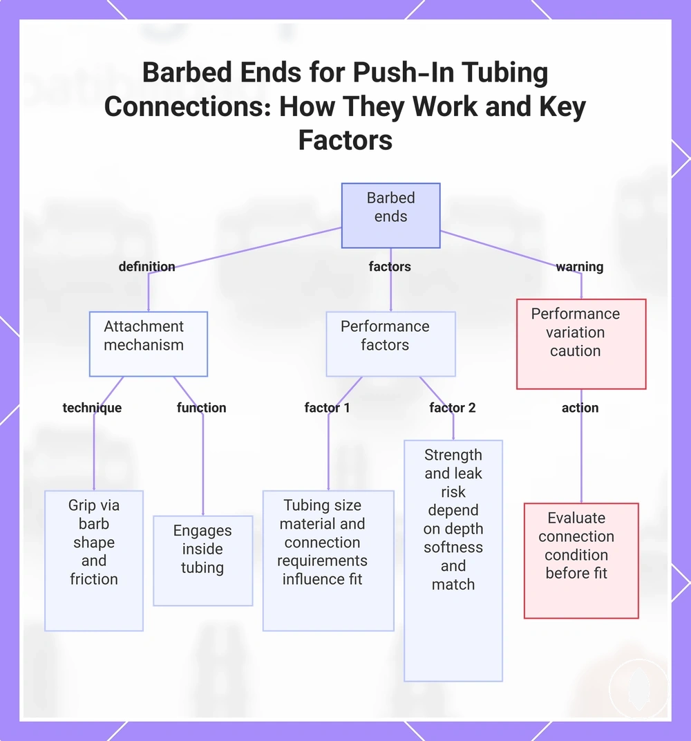
Barbed ends for push-in tubing connections
Barbed ends are attachment features that grip compatible push-in tubing through the barb shape and friction. The barbed end creates a holding connection by engaging with the inside of the tubing. The tubing fit depends on factors such as tubing size, material condition, and the connection requirements.
A push-in tubing connection may use a barbed end when the connection role requires a gripping attachment interface. Holding strength can vary with insertion depth, tubing softness, and the match between the barbed fitting end and the tubing. Leak risk can also depend on fit conditions and component compatibility.
Caution: Barbed ends may perform differently when tubing softness, size, or fitting requirements vary, so the connection condition should be considered before assessing fit.
This chart explains the definition, attachment mechanism, performance factors, and a caution for barbed ends used in push-in tubing connections.
Compression, lock, and push-fit ends for secure tubing grip
Compression ends, lock ends, and push-fit ends are attachment mechanisms that grip tubing through different holding designs. These mechanisms use different grip styles to create a secure tubing grip through compression, locking, or push-fit connection methods. The style difference matters because connector design and tubing conditions can affect the connection result.
A tubing connection held by a compression, lock, or push-fit design may respond differently depending on tubing diameter, connector design, and product standard. Secure hold and reuse potential can vary with the grip style and fit sensitivity of the connection.
| Mechanism | How it grips | Fit sensitivity | Local caution |
|---|---|---|---|
| Compression ends | Uses compression to create a holding connection around the tubing | Can depend on tubing diameter and connector design | Mismatch risk may vary with the connection conditions |
| Lock ends | Uses a locking mechanism to maintain the tubing grip | Can vary with connector design and matching components | Secure hold depends on the connection interface |
| Push-fit ends | Uses a push-fit connection design to grip tubing | Can depend on insertion conditions and tubing characteristics | Fit sensitivity may vary between components |
Threaded ends for adapters and source-side connections
Threaded ends are attachment features used when a fitting connects to another threaded interface. They allow a fitting to connect with an adapter, valve, filter, faucet-side part, or other source-side connection through a threaded interface. The connection condition depends on thread compatibility and the matching source-side part.
A threaded end may connect to a valve, filter, faucet-side part, or adapter where a matching threaded interface is required. Male thread and female thread orientations can help identify how the connection interfaces align. Thread compatibility and tubing fit are separate checks, so a suitable threaded connection does not by itself confirm the tubing connection condition.
Inlets, outlets, branches, and stops in fitting diagrams
A fitting diagram shows how openings relate to water entering, leaving, branching, or stopping at a connection point. A diagram can label the inlet, outlet, branch, and stop roles to show flow direction through a fitting. These roles help identify how each opening is interpreted.
The labels in a fitting diagram show what each opening represents and how the flow path is understood. The table below organizes diagram labels by role, opening position, flow meaning, and common fitting example.
| Diagram label | What it marks | Flow-path meaning | Common fitting example |
|---|---|---|---|
| Inlet | The opening where water enters | Shows the incoming flow direction | Entry point on a connector or fitting |
| Outlet | The opening where water leaves | Shows the onward flow direction | Exit point on a straight connection |
| Branch | The opening that creates another flow path | Shows split flow through a branch connection | Branch point on a tee fitting |
| Stop | The point where flow is closed | Shows a stopped flow path | Closure point on an end cap or plug |
A diagram position identifies a connection role, not the complete placement of every fitting in a system. For broader placement considerations, see fitting placement in layouts when interpreting how connection points relate within a larger arrangement.
Role-based checks before matching fittings to tubing
Role-based checks should come before evaluating size or example products because the fitting role determines what type of connection is being considered. Confirming the fitting role helps identify the attachment end, tubing condition, and connection point before compatibility details are assessed. This checklist verifies the main conditions that influence whether a connection is compatible, uncertain, or a mismatch.
A connection point may require a role check before comparing tubing or fitting options. The fitting role, attachment end, tubing size, and connection format provide the signals needed to understand the connection condition before moving to example products.
- Fitting role: Confirm whether the fitting joins, branches, transitions, or closes a connection point before checking other conditions.
- Attachment end: Identify the connection interface and how the fitting connects to tubing or another component.
- Tubing size: Check tubing size as a compatibility factor before assessing whether a connection may match.
- Connection format: Confirm whether the fitting and tubing or adapter use matching connection formats.
- Uncertainty signals: Identify unclear fitting style, sizing, or connection conditions that may require another check.
Size rules become relevant after the fitting role and connection type are clear. Use size and compatibility rules when evaluating size relationships and connection conditions separately. The outcome may be compatible, uncertain, or a mismatch depending on the specific components being compared.
Choosing example products from a catalog alone can hide the connection criteria that affect fit. A role check keeps example products connected to the actual connection requirements, with the main criteria being fitting role, attachment end, tubing size, connection format, and uncertainty signals.
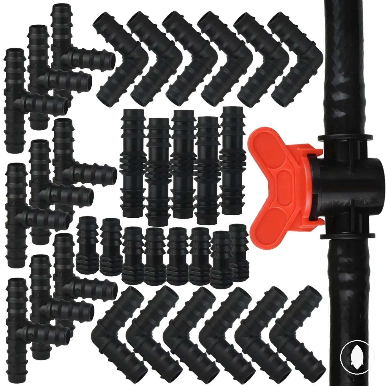
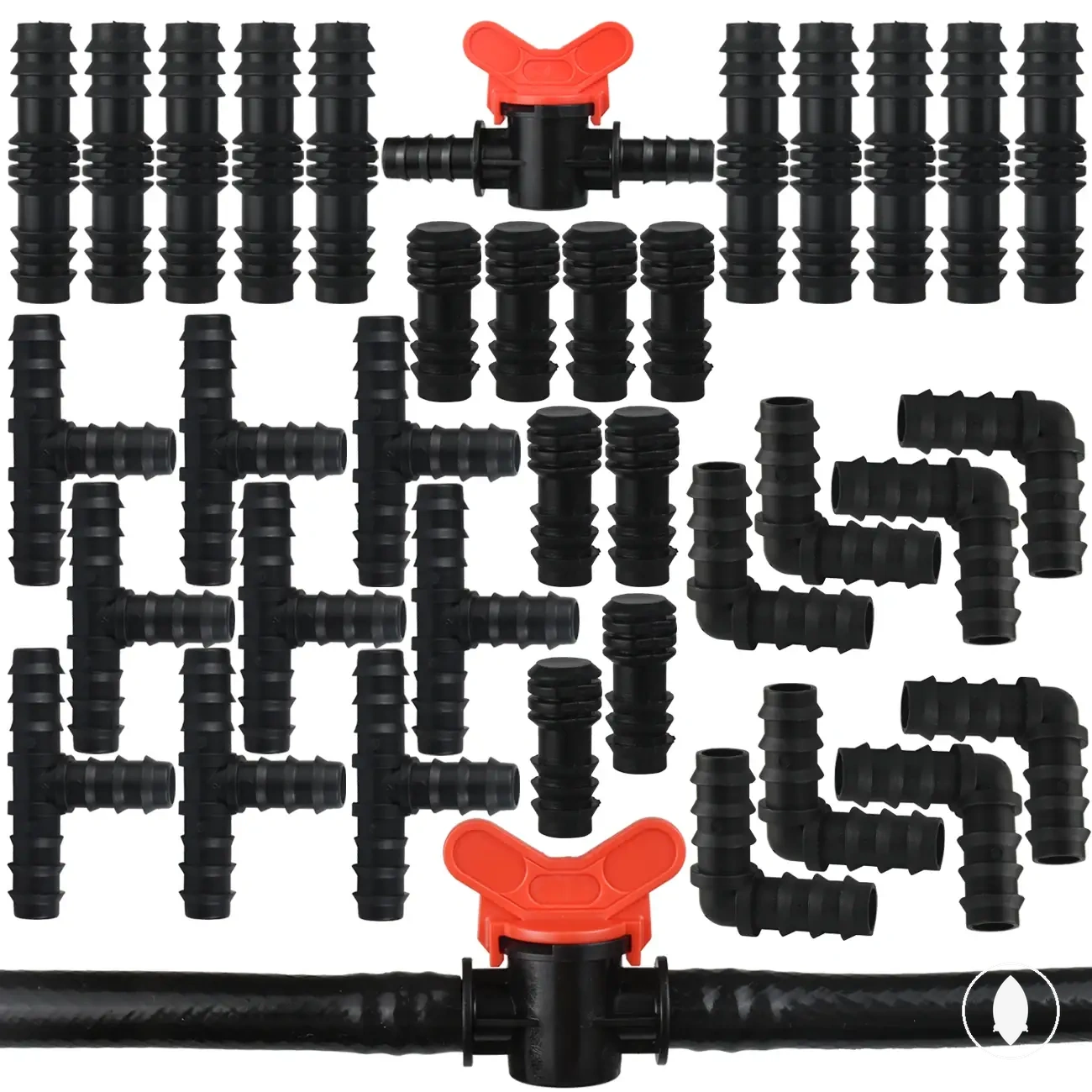
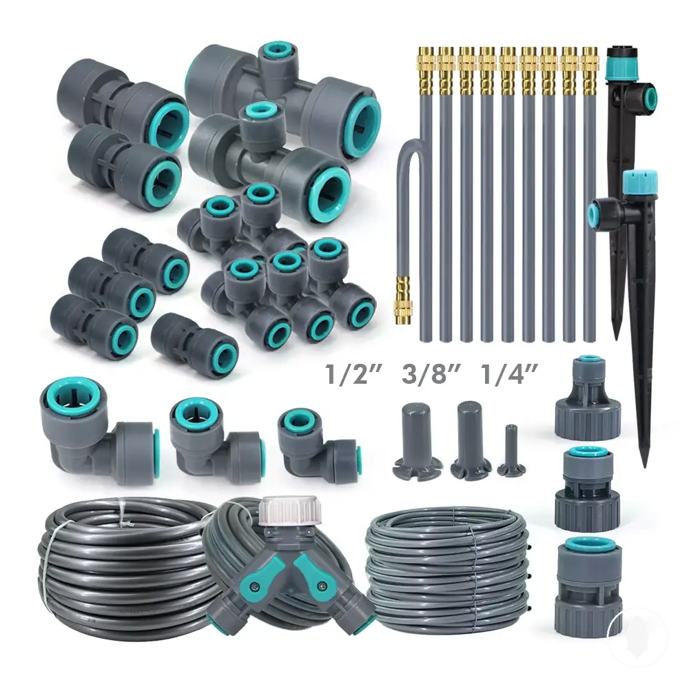
The products below are useful examples for comparing available options. Before buying, check that the compatibility criteria, key features, and product details match your needs.
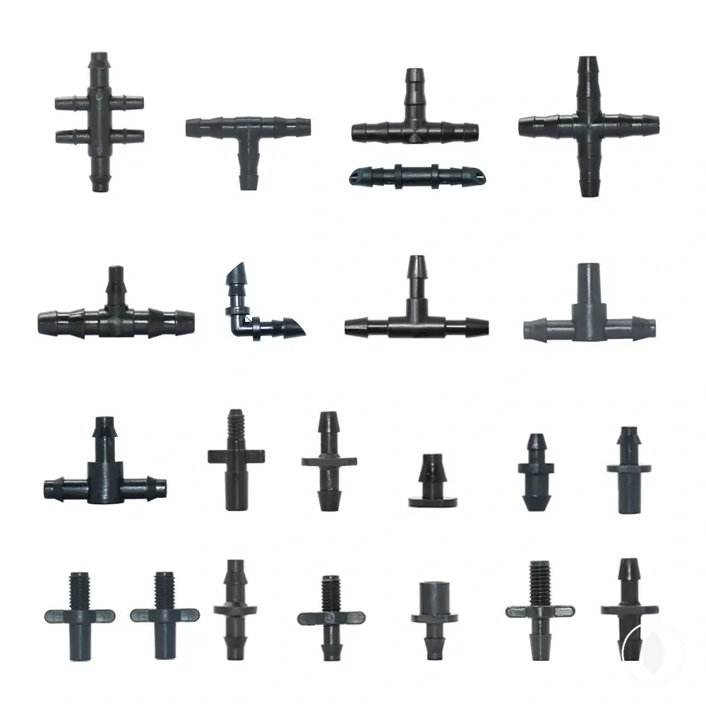
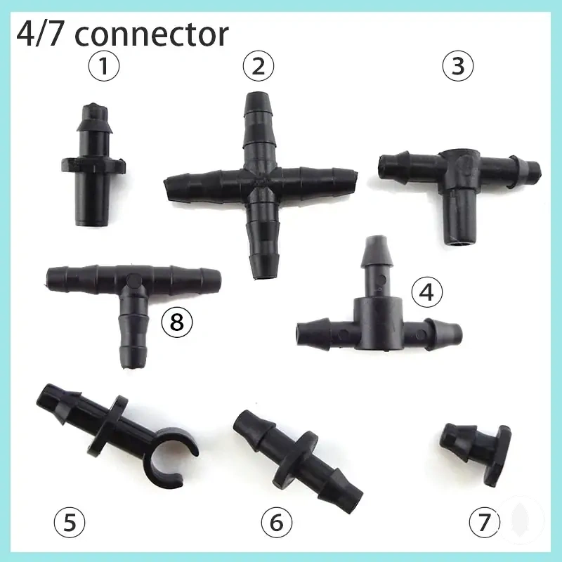
This chart shows the main checks to perform before evaluating fitting-tubing compatibility, including fitting role, attachment end, tubing size, connection format, and uncertainty signals.

Common fitting name confusion inside the correct connection role
Fitting name confusion happens because similar names can describe related parts, but the connection role should control the interpretation. A name variant may come from a supplier term, fitting style, or user shorthand rather than a single fixed naming system. The safest approach is to identify the role the part performs before interpreting the name.
A confusing supplier term or user label can often be clarified by checking the connection role instead of relying on the name alone. See drip irrigation fittings overview for broader fitting context, while this section focuses on safe interpretation within the connection role.
| Name variant | Likely connection role | Confirming condition | Next check |
|---|---|---|---|
| Coupler / repair coupling | Straight join role | The part connects tubing sections along the same path | Check the connection point and tubing condition |
| Tee | Branch connection role | The part creates another tubing path from a branch point | Check the intended branch function |
| Elbow | Direction change role | The part turns the tubing path at a connection point | Check the required turn condition |
| Adapter / reducer | Transition role | The connection requires a format or size change | Check the connection format and compatibility conditions |
| Plug / end cap / goof plug | Closure role | The part closes a line end or unwanted opening | Check whether the closure point is an end or internal opening |
The direct way to resolve a fitting name is to identify the connection role first, then confirm the attachment and compatibility conditions. This provides a safe interpretation when naming overlap exists and helps determine the next check before using the part.