
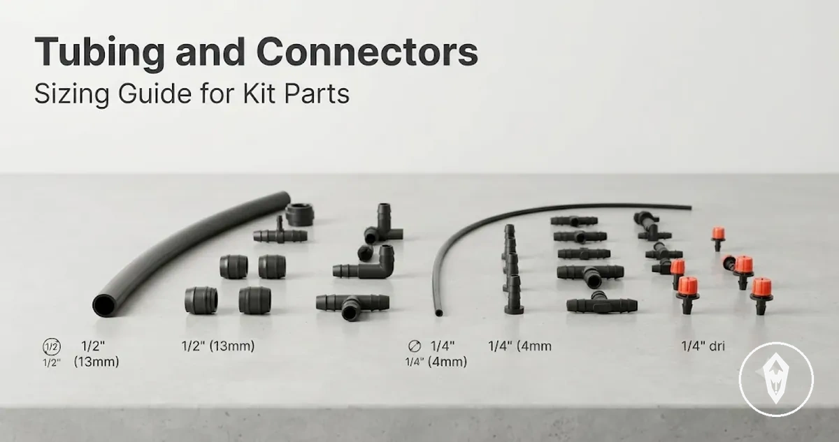
Automatic watering kit tubing and connector sizes
Automatic watering kit tubing and connector sizes define how tubing dimensions, connector fit, and layout position work together within a watering system. Tubing size and connector fit must be matched as part of the same sizing decision because fittings connect the water path between different sections of the layout.
For the wider system context, automatic watering kits include connected parts such as tubing and fittings that form a watering layout.
For the wider system context, automatic watering kits include connected parts such as tubing and fittings that form a watering layout. This page focuses on sizing relationships between tubing and connectors rather than timer setup, full installation workflows, or broader irrigation hardware.
The main sizing challenge is that a label alone may not describe the complete fit relationship.
The main sizing challenge is that a label alone may not describe the complete fit relationship. Tubing size references such as inside diameter, outside diameter, and nominal size describe different measurement points, while connector fit depends on the tubing dimensions, material characteristics, and the connector mechanism. Barbed connectors and other fittings need the relevant tubing measurement and connection method to align.
Barbed connectors and other fittings need the relevant tubing measurement and connection method to align.
Automatic watering kit tubing and connector sizes are easier to evaluate when the measurement reference and connector role are clear. The following sections explain how nominal labels, measured diameters, drip irrigation tubing, and fittings relate to layout compatibility without treating one size as a universal standard.
Table of Contents
Tubing and connectors in automatic watering kit layouts
Tubing and connectors in automatic watering kit layouts define the roles of water movement and line organization within the system. Tubing is the water path that carries water through the layout, while connectors are the junction and direction-change parts that shape how tubing sections relate to each other.
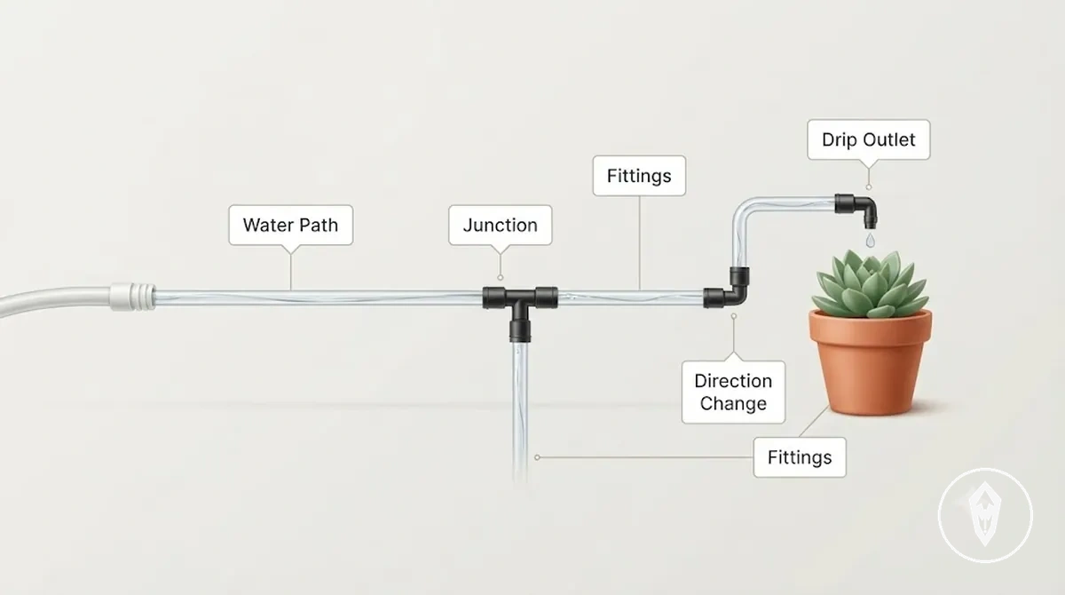
In an automatic watering kit layout, tubing creates the route from the water source area toward plant delivery points, while connectors define where that route joins, splits, turns, or ends. A tee connector creates a junction for branching lines, an elbow connector changes direction, and other fittings connect tubing according to line position, flow path, and size fit. A drip outlet represents the delivery point where water leaves the tubing path for a plant area.
Tubing and connectors are separate layout elements rather than interchangeable parts.
Tubing and connectors are separate layout elements rather than interchangeable parts. Tubing carries water through the automatic watering kit, connectors join or redirect tubing sections, and fittings act as the interface between tubing size, connection method, and layout position. Emitters, timers, filters, and pressure parts can influence the wider watering process, but they are boundary components outside the main focus of this tubing and connector layout explanation.
Tubing size standards and measurement points
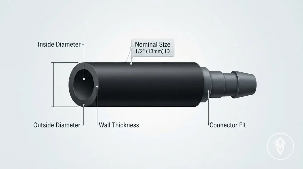
Tubing size is identified through measurement points and label conventions, so connector fit should be checked against measured tubing rather than a label alone. Automatic watering kit tubing can be described through inside diameter, outside diameter, nominal size, and wall thickness, with each measurement representing a different part of the sizing relationship.
Tubing size describes the dimensions used to evaluate how tubing connects with fittings in an automatic watering kit layout.
Tubing size describes the dimensions used to evaluate how tubing connects with fittings in an automatic watering kit layout. Inside diameter refers to the internal opening of the tubing, while outside diameter describes the external measurement used by some connector systems. Nominal size is a stated size category, and wall thickness describes the material depth between the inner and outer tubing surfaces.
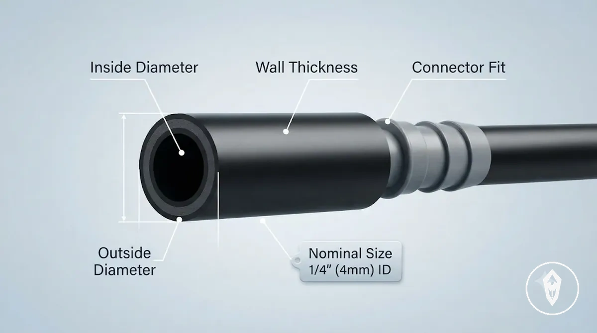
The main sizing issue occurs when similar labels do not represent the same physical measurement. Inch labels such as 1/4 inch and 1/2 inch describe tubing size categories, but connector fit can depend on the measured diameter, tubing material, wall thickness, and the fitting range of the connector.
The main sizing issue occurs when similar labels do not represent the same physical measurement.
A micro tubing section or mainline tubing section may use different size labels while still requiring the connector specification to match the measured tubing. The table below organizes measurement labels by fit decision without treating inch labels and millimetre labels as universal conversions.
| Measurement point | What it describes | Common label form | Fit decision affected |
|---|---|---|---|
| Inside diameter | The internal opening of the tubing | ID label | Internal space and connector relationship |
| Outside diameter | The external measurement of the tubing | OD label | Connector grip and fitting match |
| Nominal size | A stated tubing size category | Inch label or millimetre label | Initial size identification before physical measurement |
| Wall thickness | The material depth between inner and outer tubing surfaces | Measured dimension | Connection fit when tubing structure affects the fitting relationship |
| Connector stated range | The tubing dimensions a fitting is designed to accept | Fitting specification | Compatibility between measured tubing and connector type |
Mainline tubing, feeder tubing, and micro tubing
Mainline tubing, feeder tubing, and micro tubing are different tubing roles within an automatic watering kit layout. Each line type has a specific position in the water path, and its relative diameter influences how the layout connects supply lines, branch lines, and plant delivery points.
The three tubing types become easier to distinguish when viewed as connected sections of the same layout.
The three tubing types become easier to distinguish when viewed as connected sections of the same layout. Mainline tubing carries the main supply route, feeder tubing extends the route toward plant areas, and micro tubing forms smaller delivery branches where transition connectors may be needed to join different tubing sizes.
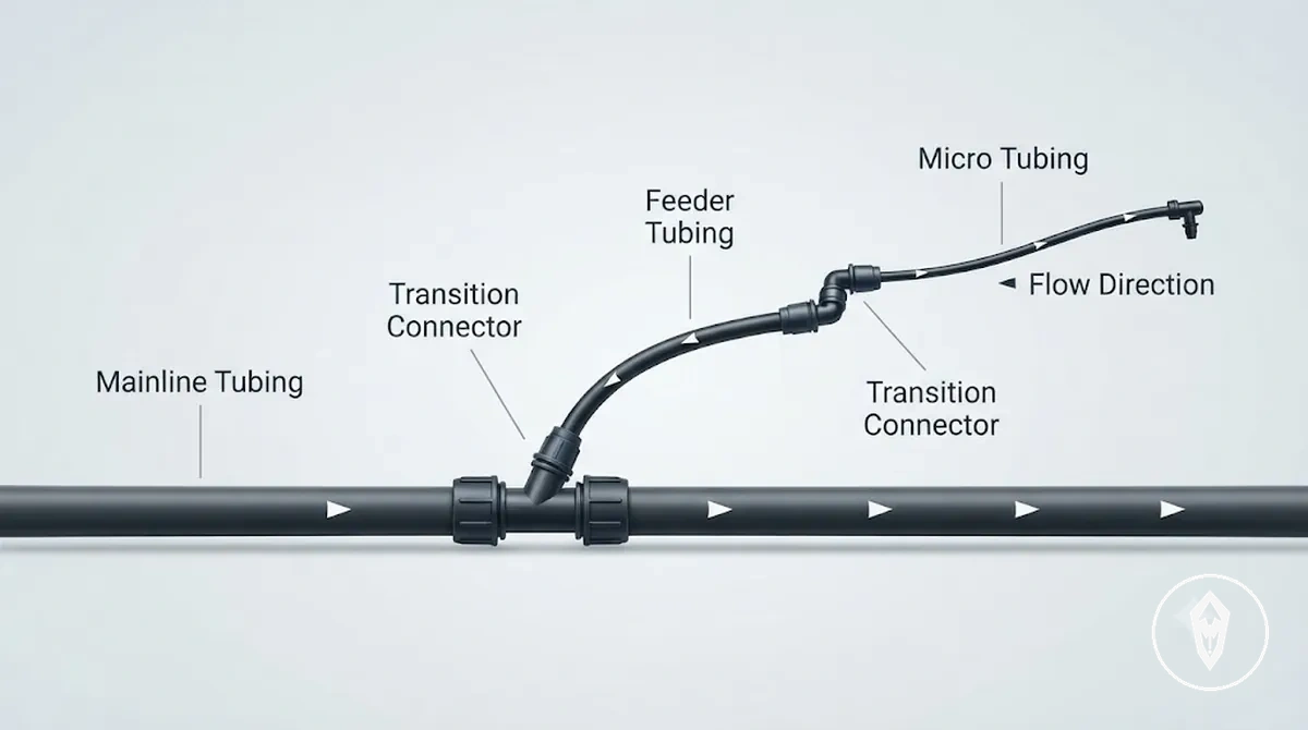
- Mainline tubing: Functions as the supply line for the main route, with a larger relative diameter role that supports branching to connected tubing sections.
- Feeder tubing: Functions as a branch line toward plant areas, with a smaller relative diameter role that connects the main route to more targeted delivery paths.
- Micro tubing: Functions as a smaller delivery line toward drip outlets, with a smaller relative diameter role that may require a transition connector when connecting to another tubing size.
Inside diameter, outside diameter, and nominal size labels
Inside diameter, outside diameter, and nominal size labels describe different measurement references used to identify automatic watering kit tubing. Inside diameter identifies the internal water path opening, outside diameter identifies the external tubing dimension, and nominal size provides a stated tubing label that must be checked against the actual measurement when evaluating connector fit.
The same tubing can be described through different measurement points, which can create confusion when matching a connector specification.
The same tubing can be described through different measurement points, which can create confusion when matching a connector specification. Wall thickness describes the material depth between the inner and outer tubing surfaces, while the relevant fit decision depends on the connector mechanism and its stated fitting range.
| Label | Describes | Fit relevance |
|---|---|---|
| Inside diameter | The internal opening and water path measurement | Relates to the flow opening and internal measurement reference |
| Outside diameter | The external tubing measurement | Relates to connector grip and fitting range requirements |
| Nominal size | A stated tubing size label or category | Provides an identification reference that should be checked against measured size |
When a tubing label does not describe the same measurement used by a connector, the connection assessment can become less clear. Checking the tubing label, measured size, wall thickness, and connector specification together helps match the measurement reference to the fitting range without assuming that nominal size represents one physical dimension in every case.
Connector fitting types by layout role
Connector fitting types are classified by the layout role they perform within an automatic watering kit. Connector fittings join tubing, create branches, change direction, reduce between sizes, or terminate a line, so the fitting role determines how it relates to the watering layout.
These examples show how connector roles differ by layout purpose.
In a wider system view, connectors work alongside automatic watering kit parts, but this section focuses on fitting functions rather than a complete component overview. A tee connector supports a branch line, an elbow connector supports a direction change, and a reducer supports a size transition between tubing sections. These examples show how connector roles differ by layout purpose.
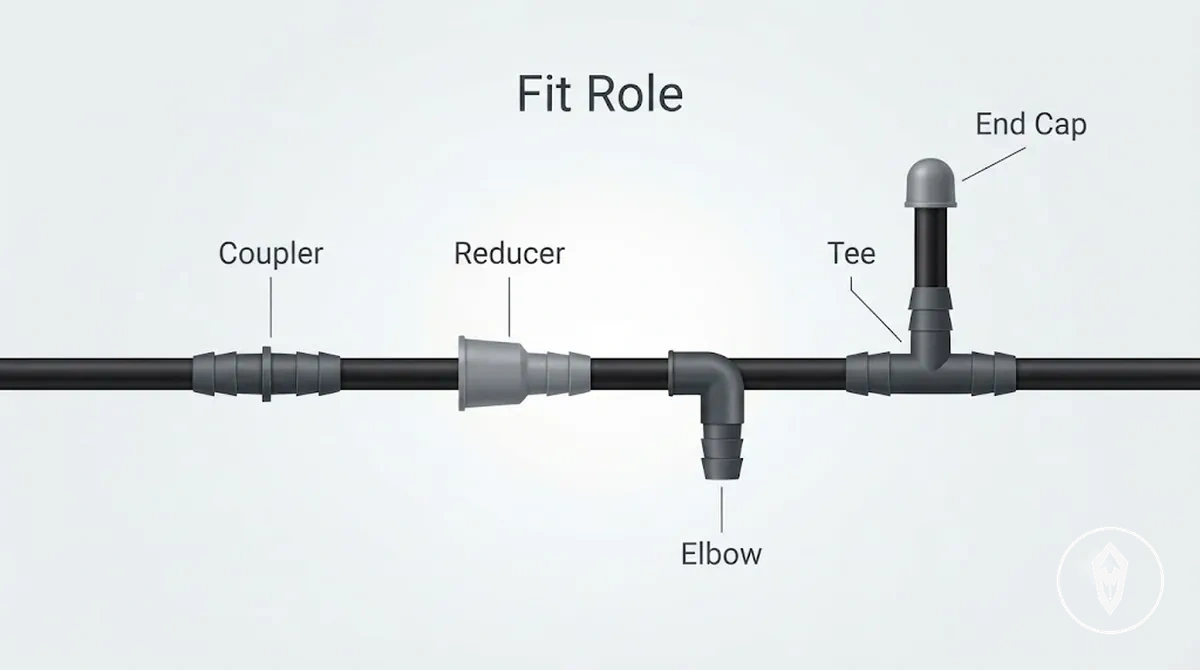
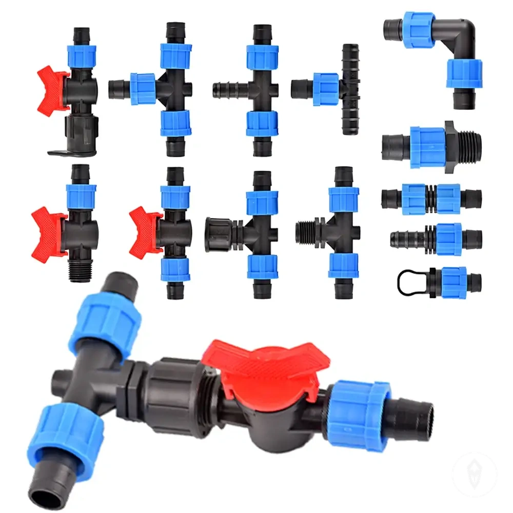
Connector fittings need to match both the movement of the layout and the tubing relationship. A coupler joins tubing sections, a tee connector splits a line, an elbow connector changes direction, a reducer adapts between tubing sizes, and an end cap closes a line end. Barbed fittings, compression fittings, and push-to-connect fittings use different connection methods, so tubing size, material, and fitting design affect their suitability for a specific layout condition.
Connector fitting types by layout role can be compared by the job each fitting performs.
Connector fitting types by layout role can be compared by the job each fitting performs. The table below organizes fittings by their layout purpose, fit condition, and the possible result when the fitting does not match the tubing arrangement.
| Fitting type | Layout role | Size or fit condition | Risk if mismatched |
|---|---|---|---|
| Coupler | Joins two tubing sections | Requires compatible tubing dimensions and connection method | Connected sections may not align with the intended layout |
| Tee connector | Creates a branch line split | Requires compatible tubing sizes at each junction point | Branch connections may not match the layout structure |
| Elbow connector | Creates a direction change | Requires suitable tubing connection for the turn location | The tubing route may not match the intended direction |
| Reducer | Creates a size transition between tubing sections | Requires compatible larger and smaller tubing connections | The size transition may not connect correctly |
| End cap | Terminates a line end | Requires compatibility with the tubing end | The line ending may not match the layout requirement |
| Barbed fitting | Provides a tubing grip connection | Requires suitable tubing size and material for the fitting mechanism | The connection suitability may be reduced |
| Compression fitting | Uses a compression connection method | Requires a compatible tubing relationship and fitting range | The connection may not match the tubing requirement |
| Push-to-connect fitting | Uses a push-fit connection method | Requires compatible tubing dimensions and fitting specification | The connection may not match the intended layout |
Couplers, tees, elbows, reducers, and end caps
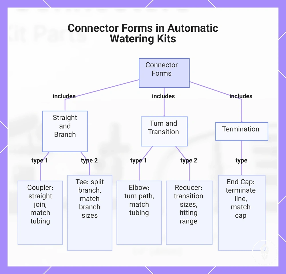
Couplers, tees, elbows, reducers, and end caps are connector forms classified by their layout role within an automatic watering kit. The sorting logic is based on whether a connector needs to join, branch, turn, transition, or terminate a tubing section.
- Coupler: Joins two tubing sections in a straight run where the line continues forward; sizing depends on matching the tubing dimensions and connection method.
- Tee connector: Splits a main line into a branch where an additional route is needed; sizing depends on the tubing sizes connected at the branch points.
- Elbow connector: Turns the tubing path at a bend or corner location; sizing depends on the tubing dimensions and the connector mechanism used for the turn.
- Reducer: Transitions between different tubing sizes where larger and smaller lines meet; sizing depends on the measured tubing sizes and the fitting range of the reducer.
- End cap: Terminates a line end where the tubing route stops; sizing depends on matching the cap connection to the tubing end and termination requirement.
This chart shows the main connector types in automatic watering kits, grouped by their layout role: joining, branching, turning, transitioning, and terminating.
Barbed, compression, and push-to-connect fittings
Barbed, compression, and push-to-connect fittings use different holding mechanisms to connect tubing within an automatic watering kit. The fitting mechanism affects how tubing is gripped and sealed, which makes the holding method an important part of fit evaluation.
Each connection method has different tubing conditions that influence the connection outcome.
Each connection method has different tubing conditions that influence the connection outcome. Checking the tubing condition, connector specification, and fitting range together helps identify situations where grip, insertion, seal, or looseness risk may need further consideration.
| Fitting mechanism | Tubing condition needed | Fit risk to watch |
|---|---|---|
| Barbed fitting | Flexible tubing suitable for the barb insertion method | Grip may be affected if tubing size, material, or insertion fit does not match |
| Compression fitting | Tubing that matches the compression connector specification | Seal performance may be affected if tubing condition or fitting range is unsuitable |
| Push-to-connect fitting | Tubing with a suitable end condition for the push-fit mechanism | Connection security may be affected if tubing dimensions or connector specification do not align |
Matching connector size to tubing before assembly
Connector size and tubing outside diameter must match the connector's stated fitting range or connection mechanism before assembly begins. A measured tubing size check helps reduce loose connections and forced fits because the connector must hold the tubing according to its intended fit method.
A connector may appear similar in size while still using a different fitting requirement.
A connector may appear similar in size while still using a different fitting requirement. Barb size, compression range, and push-fit requirements affect how tubing is held and sealed, so tubing flexibility and the connector specification should be checked together. A loose fit and a forced fit create different concerns: loose tubing may not grip correctly, while forced insertion may stretch tubing or place stress on the connection.
A reducer or transition fitting should match the measured tubing dimensions rather than being used to force incompatible tubing sizes together.
When a mainline, feeder, or micro tubing section uses a different size relationship, a reducer can provide a size transition when the connector design supports that change. A reducer or transition fitting should match the measured tubing dimensions rather than being used to force incompatible tubing sizes together.
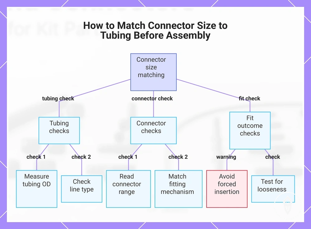
Matching connector size to tubing before assembly can be verified through a short fit checklist.
Matching connector size to tubing before assembly can be verified through a short fit checklist. For broader information about connector compatibility, use these checks to confirm the tubing and connector relationship before insertion.
- Measure tubing OD: Confirm the tubing outside diameter used for the connection.
- Read connector range: Check the stated fitting range, barb size, or compression range.
- Check line type: Match the connector to mainline, feeder, or micro tubing use.
- Match fitting mechanism: Confirm the tubing condition suits the connector method.
- Avoid forced insertion: Do not force a connector when the tubing size or flexibility does not align.
- Test for looseness: Check that the tubing and connector relationship is suitable before relying on the connection.
This chart shows the key checks to verify connector and tubing size compatibility before assembly, including tubing measurement, connector specification, and fit verification.
Conflicting inch and millimetre size labels
Inch label and millimetre label differences can create confusion because a nominal size may describe a size category rather than the same physical measurement. Checking the nominal size against the actual diameter helps clarify whether the label represents the measured tubing needed for a connector fit.
The measured tubing and connector range remain the deciding references when checking whether a fitting relationship is suitable.
Similar-looking size labels do not confirm the same fit result because equivalent size descriptions can still have different physical dimensions. The measured tubing and connector range remain the deciding references when checking whether a fitting relationship is suitable.
| Label says | Fit check still needed |
|---|---|
| Inch label | Compare the nominal size with the actual diameter and connector range before fitting |
| Millimetre label | Confirm the measured tubing dimension and fitting range for the connection |
| Equivalent size | Verify physical fit because a similar label does not confirm interchangeable sizing |
Tubing length and branching effects on connector choice
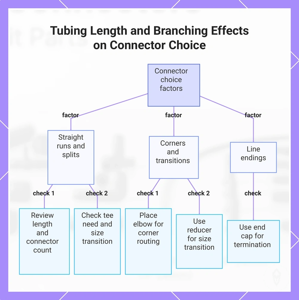
Tubing length and branching affect connector choice because layout features such as long runs, line splits, turns, and size transitions require different connector roles. A longer tubing run can change the number of connection points needed, while branch count can determine whether a tee connector or another fitting type is required.
These layout conditions influence branching and corner-routing decisions before connector selection.
A simple pot run usually has fewer layout changes, while a branched balcony layout may require a tee connector where a split line is created. A corner-heavy garden layout may require an elbow connector for corner routing, while a reducer can support a size transition between different tubing sections. These layout conditions influence branching and corner-routing decisions before connector selection.
These considerations relate to layout stability rather than broader capacity or pressure topics.
When a layout creates multiple connection points, the connector choice should match the specific tubing behavior and position. A long run may require attention to connector count and fit risk, while split lines, tight corners, and line endings each create different connection requirements. These considerations relate to layout stability rather than broader capacity or pressure topics.
Tubing length and branching effects on connector choice can be organized into a short decision checklist.
Tubing length and branching effects on connector choice can be organized into a short decision checklist. The checklist connects common layout features with connector decisions so the next step is selecting fittings that match the tubing arrangement.
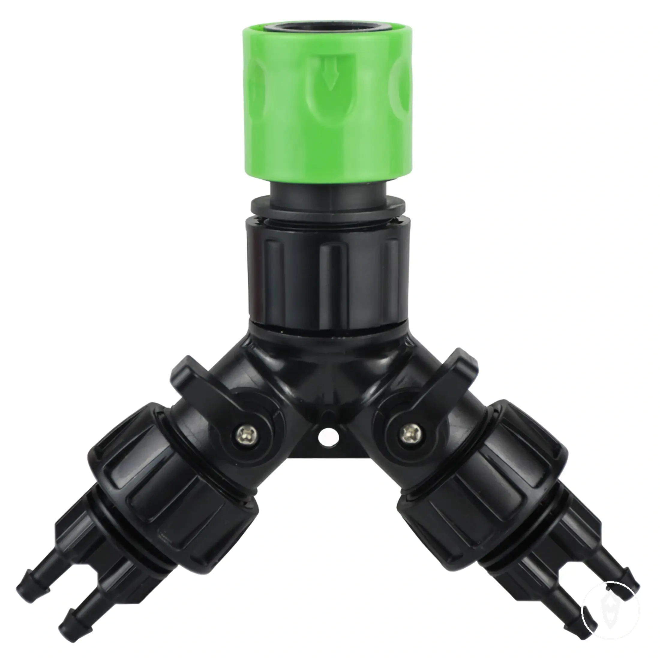
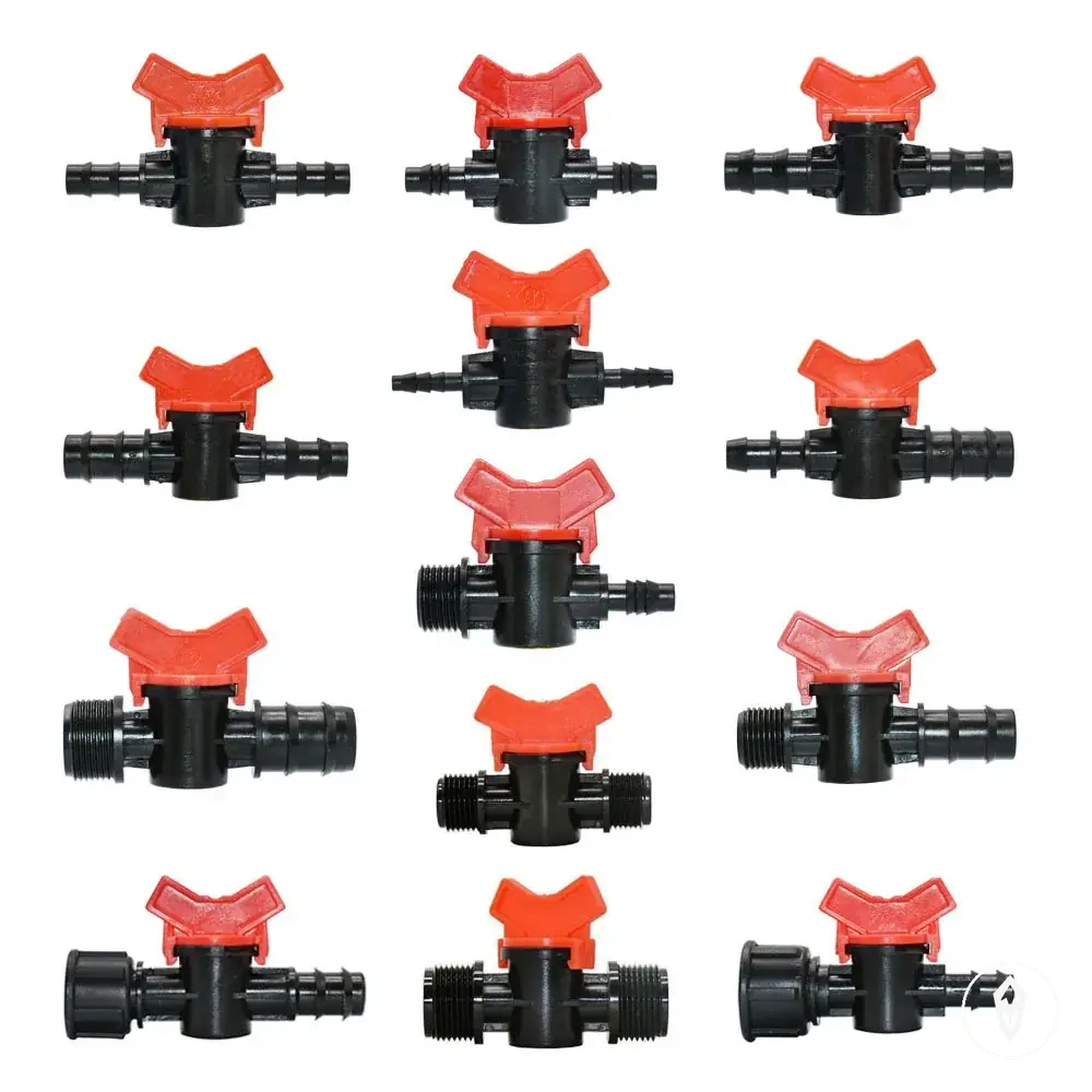
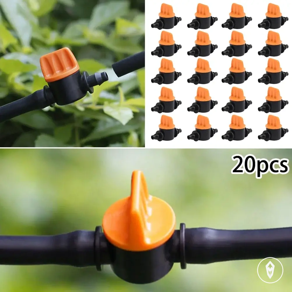
The products below are useful examples for comparing available options.
The products below are useful examples for comparing available options. Before buying, check that the compatibility criteria, key features, and product details match your needs.
- Long run: Review tubing length and connector count; fit depends on matching tubing sections and connection points.
- Branch count: Check whether a tee connector is needed for a split line; sizing depends on the connected tubing sections and size transition.
- Turns: Consider elbow connector placement for corner routing; fit depends on tubing position and connector design.
- Reductions: Use a reducer where a size transition is required; matching depends on the mainline, feeder, or micro tubing relationship.
- Line endings: Consider an end cap for termination points; fit depends on matching the connector to the tubing end.
This chart shows how layout features like long runs, branch counts, turns, reductions, and line endings influence connector selection, with a checklist for each condition.
Connecting tubing without damaging the fit
Connecting tubing without damaging the fit requires a clean cut, correct connector orientation, and controlled insertion pressure. Clean cuts and careful insertion protect the tubing end and connector grip by maintaining the intended fit relationship.
Clean cuts and careful insertion protect the tubing end and connector grip by maintaining the intended fit relationship.
A square cut creates an even tubing end for connection, while a damaged or uneven end can affect how the connector sits inside the tubing. The tubing end should be clean before insertion, and softened tubing should only be used when the material and connector method are suitable for that approach.
Different tubing conditions can change how a connection should be handled.
Different tubing conditions can change how a connection should be handled. If insertion requires excessive force, stretched tubing can occur and may contribute to later looseness because the tubing shape has been altered. Signs such as a distorted tubing end, loose connector, or visible fit damage indicate that the connection should be checked again.
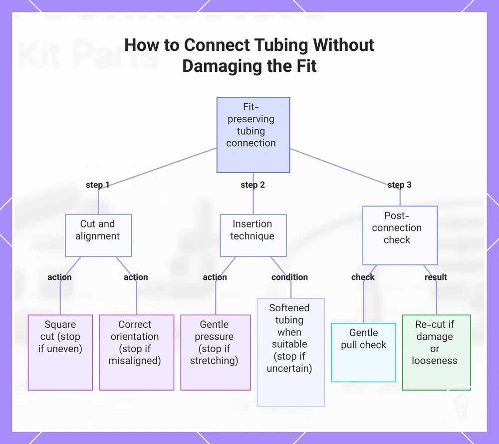
Connecting tubing without damaging the fit can be completed with a short fit-preserving connection check.
Connecting tubing without damaging the fit can be completed with a short fit-preserving connection check. For the broader process to install tubing and connectors, use the installation guidance for the complete workflow beyond these local connection steps.
- Create a clean cut: Make a square cut on the tubing end so the connector meets an even surface; stop if the tubing edge is uneven or damaged.
- Align connector orientation: Position the connector correctly before insertion to support the intended seal; stop if the connector does not align with the tubing path.
- Control insertion pressure: Insert the connector with gentle pressure instead of forcing the fit; stop if the tubing stretches or changes shape.
- Use softened tubing when appropriate: Warm-water or sun-softening may help with suitable tubing materials; stop if the material response is uncertain or the tubing becomes distorted.
- Perform a pull check: Apply a gentle pull check after connection to identify looseness or fit concerns; re-cut the tubing end if damage affects the connection surface.
This chart shows the key steps and warnings for connecting tubing while preserving the fit, including cut preparation, insertion technique, and post-connection check.
Common fit problems from wrong tubing or connector size
Fit problems from wrong tubing or connector size commonly appear as leaks, loose connections, hard insertion, kinks, or uneven water delivery. Wrong connector size can create these symptoms, but pressure conditions, debris, emitters, installation, and maintenance can also contribute.
A loose fit and a forced fit create different connection issues.
A loose fit and a forced fit create different connection issues. A loose connection may occur when tubing does not match the connector relationship, while a forced fit can create stretched tubing and future looseness because the tubing shape has changed.
A tubing or connector mismatch can appear differently depending on the fitting condition.
A tubing or connector mismatch can appear differently depending on the fitting condition. An incorrect reducer may affect a size transition, a tight elbow connector may contribute to a kink during corner routing, and a poorly matched barb may reduce the intended tubing grip.
The table below focuses on fit-related causes while separating them from broader system factors.
Common fit problems from wrong tubing or connector size can be reviewed through a diagnostic check that connects symptoms with possible size or connector issues. The table below focuses on fit-related causes while separating them from broader system factors.
| Symptom | Likely fit issue | Check | What it means |
|---|---|---|---|
| Leak | Loose barb or wrong connector size | Check tubing fit and connector relationship | The connection may not be holding the tubing as intended |
| Loose connection | Tubing and connector size mismatch | Check for stretched tubing or an unsuitable fitting | The connector may not maintain the intended grip |
| Hard insertion | Oversized fitting or unsuitable tubing condition | Check connector size and tubing flexibility | Forced insertion may stretch tubing and affect later fit |
| Kink | Tight elbow connector or unsuitable corner routing | Check the tubing path and connector position | The layout may restrict the tubing shape |
| Uneven water delivery | Possible tubing or connector issue | Check connections before broader system checks | The cause may extend beyond tubing-size matching |
Fit-focused diagnostic checks can identify tubing and connector size issues, but persistent symptoms may require broader troubleshooting. For issues beyond tubing-size checks, review leaks and clogs in tubing to consider other possible causes of ongoing problems.